When the Shortest Path Is Not the Current Path
A technical-depth note on current distribution in overhead-line corridors under 50 Hz fault and lightning impulse conditions.
The same overhead-line corridor can behave like a distributed earthing network under 50 Hz earth-fault conditions, but like a local impulse-current problem under lightning conditions. That difference changes current paths, touch-voltage risk, and infrastructure stress.
Key takeaways
- Current distribution in linear infrastructure is not only a location problem; it is a source-regime problem.
- At 50 Hz, an overhead-line corridor can share fault current across many mast earthing systems.
- Under lightning impulse conditions, most of the current may remain close to the injection point.
Current distribution in overhead-line corridors under fault and lightning conditions.
Introduction
In power-system and lightning-protection studies, it is tempting to imagine current flow in a simple way: the current enters a structure, finds the shortest or “best” path to earth, and disappears mainly through the nearest earth-termination system.
For a single mast of an overhead transmission line, this intuition leads to a common expectation: during an earth fault, most of the current should enter the affected mast foundation and return locally through its earthing system.
But linear infrastructure does not behave like an isolated electrode.
An overhead-line corridor is an electrically coupled system: lattice masts, earth wires, phase conductors, tower footings, soil layers, substation earthing systems, and nearby infrastructure all form part of the same electromagnetic environment. The current distribution depends not only on geometry, but also on the source regime.
A 50 Hz earth fault and a lightning impulse may use the same physical corridor, the same masts, and the same earthing systems — but they do not necessarily use the same return path.
To make this effect visible, let us look at a simple representative example: a 220 kV overhead-line corridor with lattice masts, an overhead earth wire, a phase conductor, non-uniform mast earthing, and equivalent terminations at both corridor ends.
Three operating regimes are compared:
- a 50 Hz earth fault with predominantly ohmic current redistribution,
- a 50 Hz earth fault including coupling with the phase conductor,
- a 10/350 µs lightning impulse applied to the same corridor.
The goal is to show a practical engineering effect: the same infrastructure can produce completely different current distributions depending on whether the excitation is a power-frequency fault or a lightning impulse.
This matters for mast-foot touch voltages, earthing assessment, surrounding pipelines, cable systems, railway infrastructure, fences, and surge-protection design.
The example corridor
The example is intentionally simple: a representative 220 kV overhead-line corridor between two substations. The corridor includes lattice masts, one overhead earth wire, one phase conductor, and individual mast earthing systems.
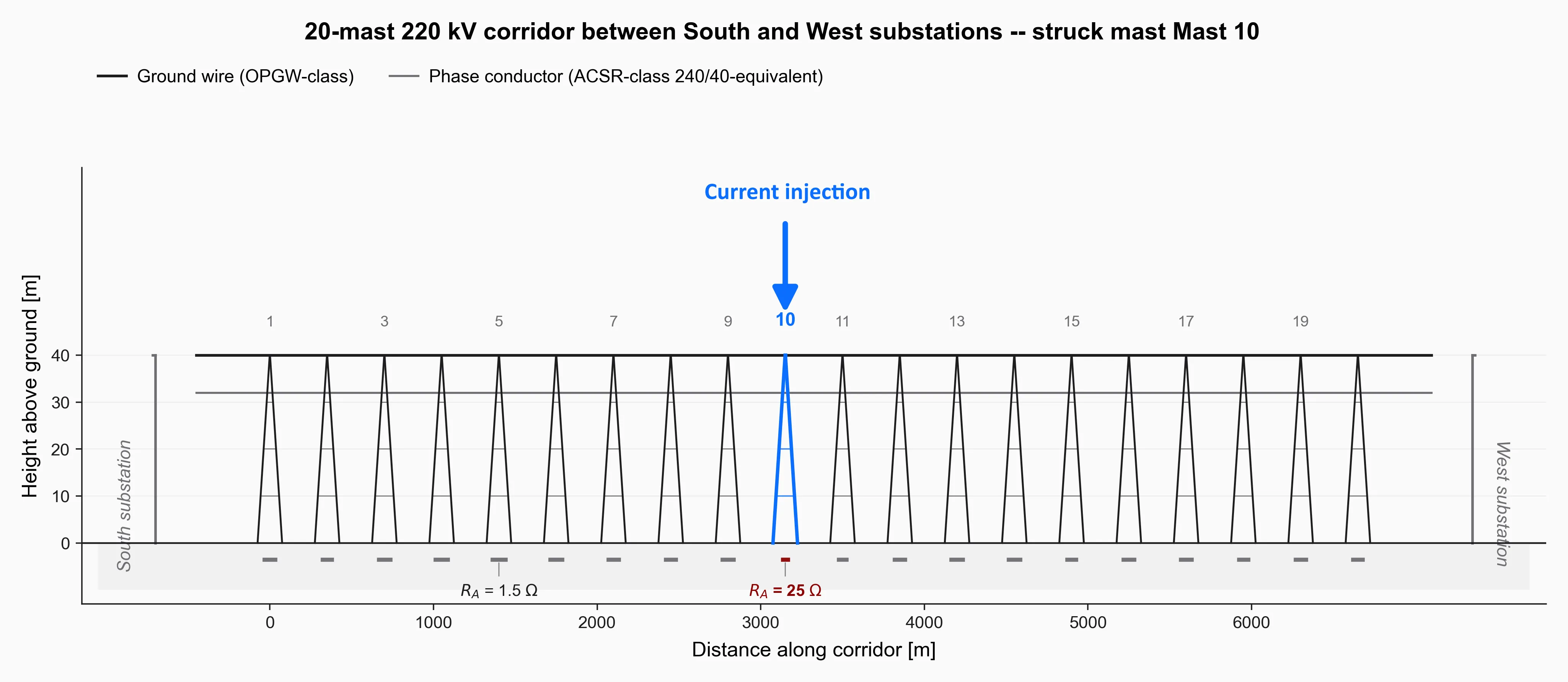
Representative multi-mast corridor used to compare 50 Hz fault behaviour and lightning impulse behaviour on the same physical geometry.
Mast 10 is selected as the current-injection point. This allows the same geometry to be compared under different source regimes: a 50 Hz earth fault and a lightning impulse.
To make the example more interesting, the mast earthing resistances are not assumed to be uniform. This is important, because real corridors rarely have identical soil and earthing conditions at every mast. In the example, one mast has a very low earth resistance, while the injection mast has a comparatively high value. This creates a useful test case: does the current stay close to the injection point, or does it move along the corridor to find a better return path?
Same corridor, three source regimes
The same corridor is compared under three different source regimes:
- ohmic redistribution of an earth-fault current,
- a 50 Hz fault with phase-conductor coupling included,
- a lightning impulse at Mast 10.
The first case represents the classical “earth-wire ladder” view. The second adds electromagnetic coupling between phase conductor and overhead earth wire. The third changes the problem completely: due to the high-frequency content of the lightning impulse, the inductive impedance of the overhead earth wire becomes dominant.
Same geometry. Same earthing systems. Different source regime — different current path.
The big picture in one image
Before looking at individual mast currents, it helps to look at the soil-surface potential around the corridor.
The figure below shows the same corridor under the three source regimes. The geometry is unchanged. The earthing systems are unchanged. Only the source regime changes.
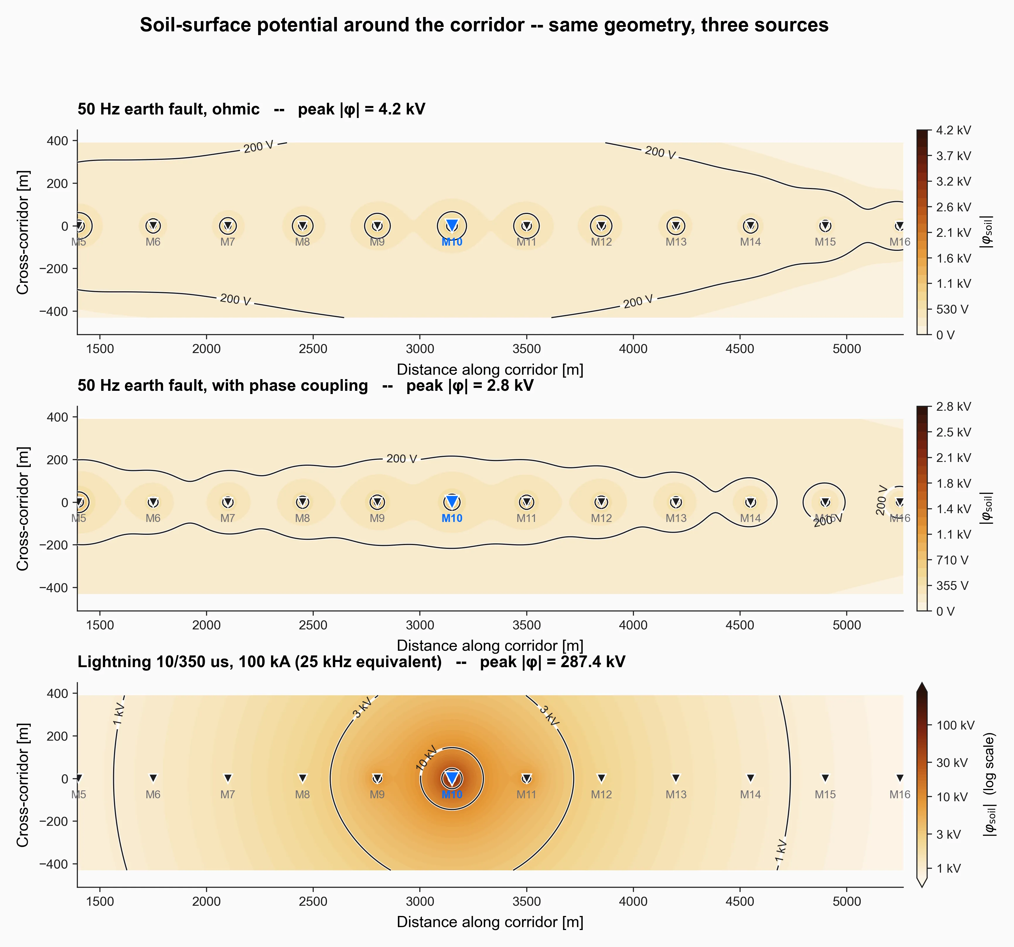
Soil-surface potential for the same corridor under ohmic redistribution, 50 Hz phase coupling, and lightning impulse conditions.
The difference is immediately visible.
In the ohmic redistribution case, the potential distribution is broad. The corridor behaves like an electrically connected system, and the return current spreads over a large part of the line.
In the 50 Hz fault case with phase coupling, the picture becomes more structured: each mast produces a more local potential rise, and the overall earth-current contribution is reduced.
Under lightning impulse conditions, the behaviour changes completely. The potential rise is concentrated around Mast 10 (almost like a bullseye around Mast 10). The corridor no longer behaves like a low-impedance current-distribution ladder; the impulse remains mainly local.
This is the key message of the article:
same corridor, same earthing systems — but a completely different current path.
Result 1 — 50 Hz current “sees” the whole earthing network
The 50 Hz case is already less intuitive than expected.
At the injection mast, the current does not “see” only the local mast earthing system. Through the overhead earth wire, it also sees the neighbouring mast earthings in both directions.
In simple terms: many mast earthing systems work together as a distributed parallel return path.
That is why the current does not necessarily leave the structure where the fault is applied.
In the ohmic case, Mast 10 carries about 8.9% of the injected fault current. But Mast 5, located several spans away, carries about 10.1%.
Why? Because Mast 5 has the lower earth resistance. For the current, it is simply the more attractive exit into the ground.
When the phase conductor is included, the share at Mast 10 becomes even lower. This shows that coupling between the phase conductor and the overhead earth wire can noticeably change the current returning through the mast earthing systems.
At 50 Hz, the corridor shares the problem.
The fault location is important — but it is not the whole story.
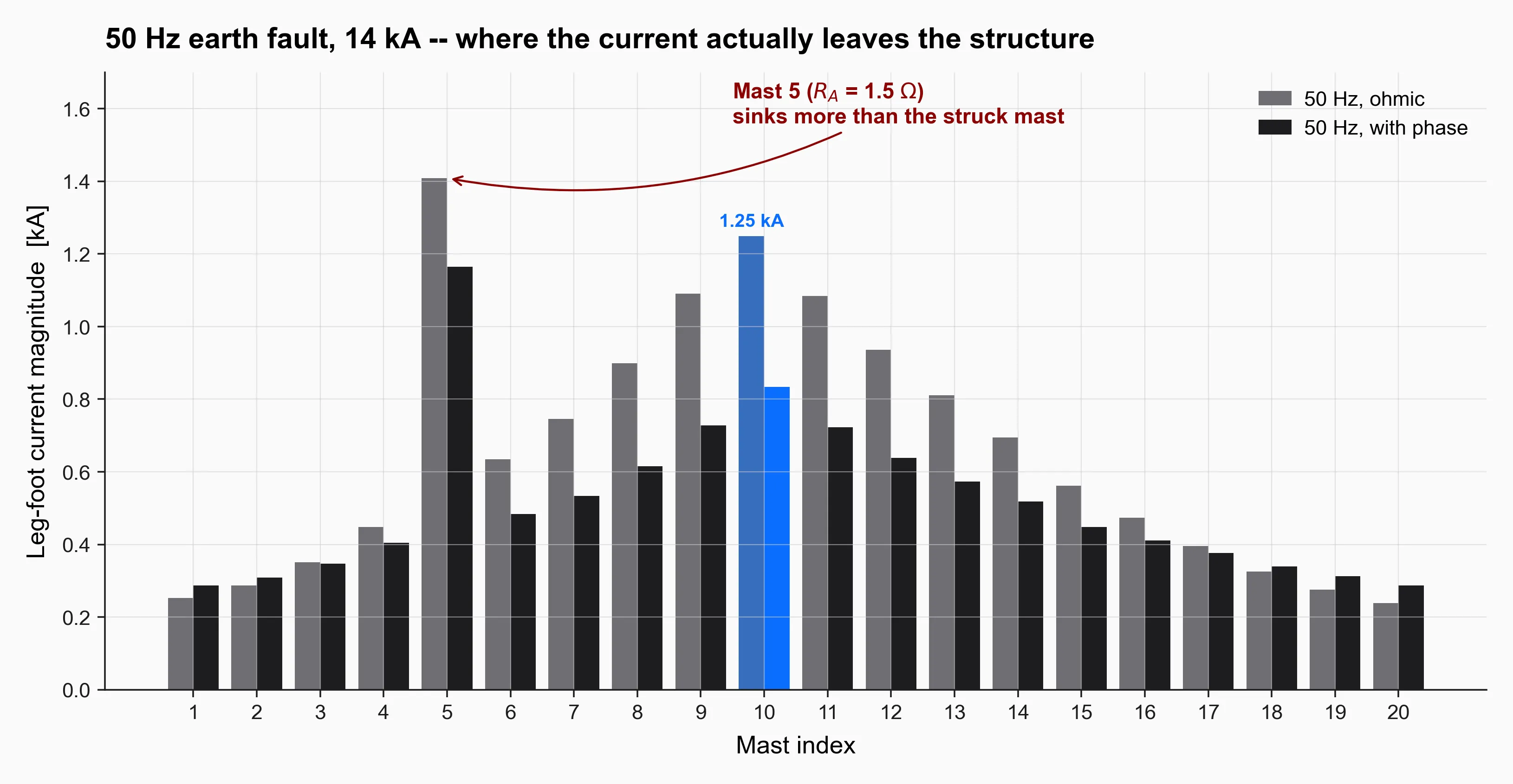
Per-mast leg-foot current for the two 50 Hz cases, showing how the corridor participates as a distributed return path.
Result 2 — lightning current stays local
The lightning case looks completely different.
For the 10/350 µs impulse, Mast 10 carries about 89% of the injected current. The direct neighbours still participate, but after a few spans the current contribution becomes very small.
Why?
At 50 Hz, the overhead earth wire behaves like a low-impedance connection between the mast earthing systems. The corridor helps the current to spread.
Under lightning conditions, the high-frequency content changes the game. The inductive impedance of the overhead earth wire becomes dominant, and every span adds impedance.
So the impulse current does not “walk” along the corridor in the same way. It mostly stays where it enters.
That makes the local earthing system of the injection mast much more important — for potential rise, touch-voltage risk, and stress on nearby infrastructure.
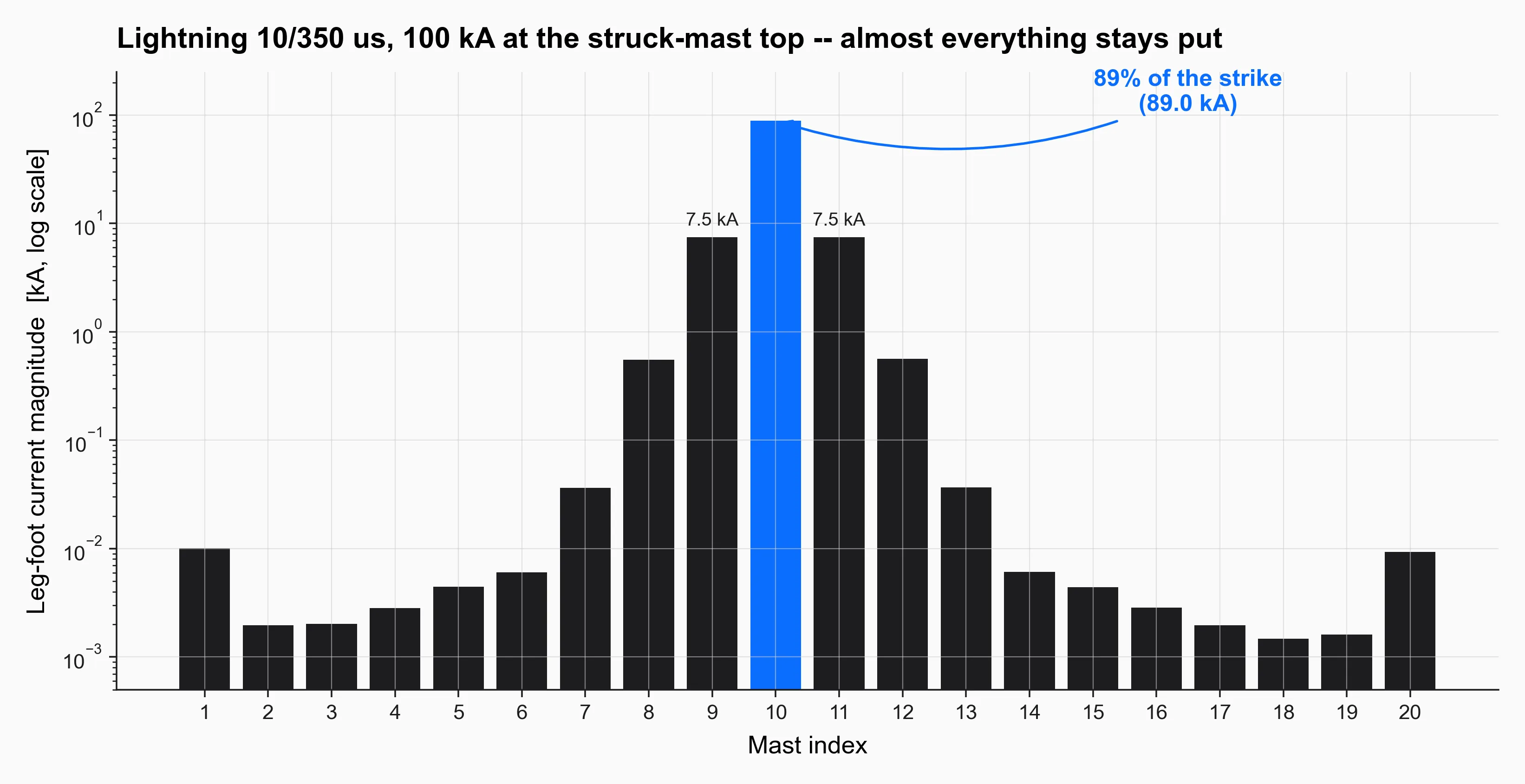
Per-mast leg-foot current for the lightning case, where most of the injected impulse current remains close to Mast 10.
Result 3 — current distribution becomes a safety question
Touch voltage directly at the mast foot is often not the main practical work scenario. In many cases, people are not expected to touch a transmission mast during a fault.
But the mast-foot result is still useful as a demonstration example: it shows how local potential rise and current distribution can become a safety question for nearby infrastructure.
Realistic examples are:
- a technician working at a pipeline test post,
- personnel handling a cable sheath, telecom or LWL route,
- a fence, gate, cabinet or junction box close to the affected line section,
- a pipeline corridor or railway system running near the overhead line.
For orientation, assume a short fault-clearing time of 250 ms and a reference level of about 1 kV for prospective touch voltage.
At Mast 10, the calculated value is clearly above this level in both 50 Hz cases.
The practical message:
A mast does not need to carry the largest share of the total fault current to become safety-critical.
A high local earthing resistance can still create a critical local potential rise — and nearby infrastructure may be affected as well.
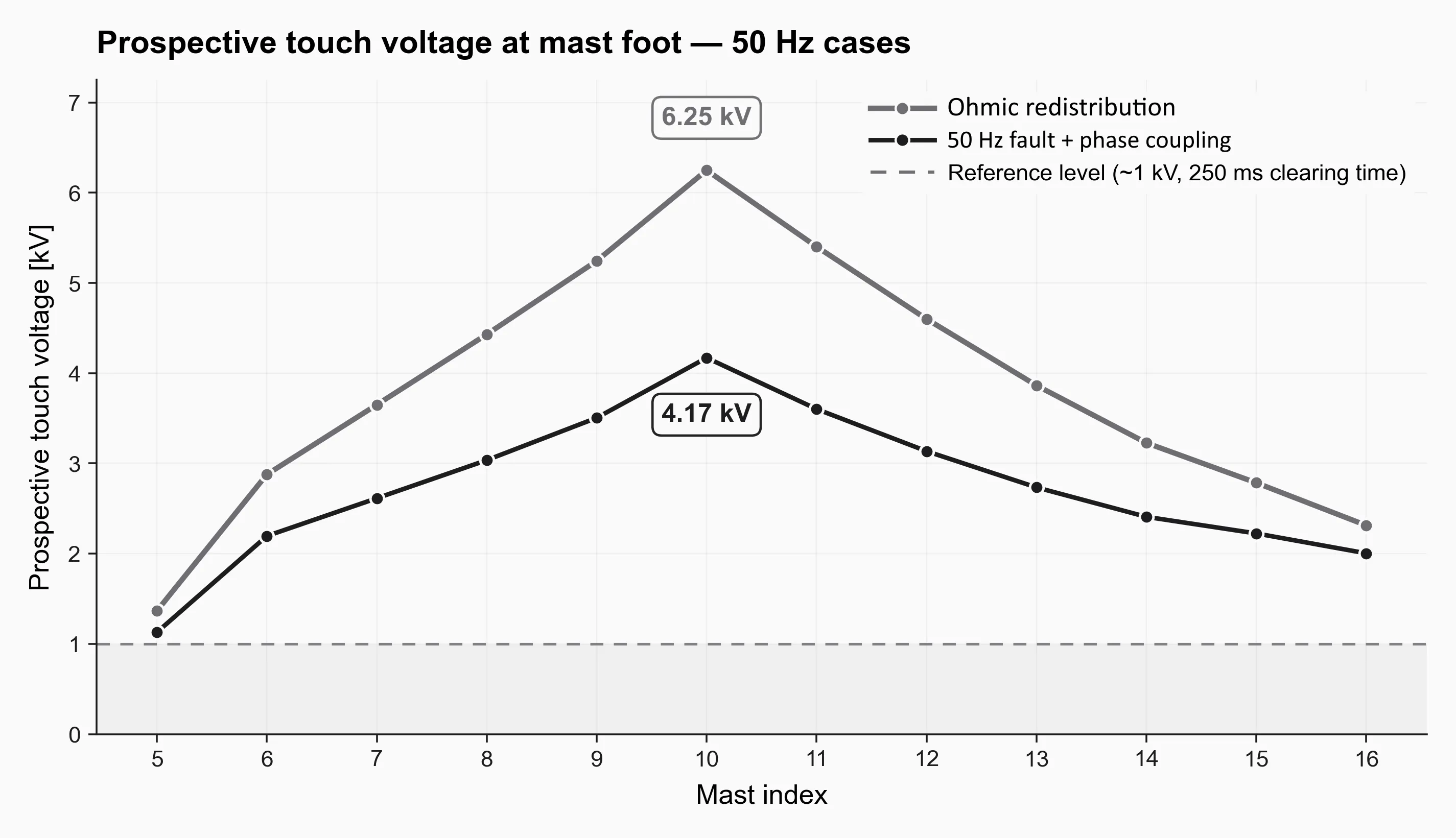
Worst-case prospective touch voltage at each mast foot for the 50 Hz cases, illustrating why current distribution becomes a safety question.
Result 4 — the punchline: same corridor, different current path
Here is the whole story in one view.
In the ohmic case, the current spreads over the corridor.
With phase-conductor coupling included, the distribution changes again.
Under lightning impulse conditions, the picture flips: most of the current stays close to Mast 10.
Same corridor.
Same earthing systems.
Different source regime.
Different current path.
Different infrastructure stress.
Different safety risk.
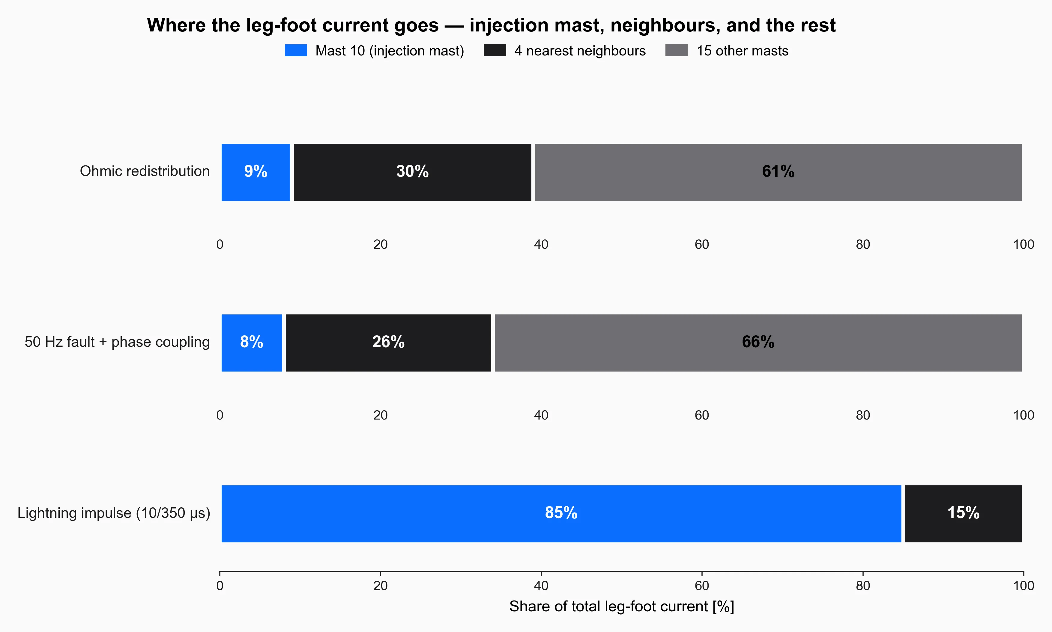
Current sharing across the injection mast, nearby masts, and the rest of the corridor for each source regime.
| Case | Struck mast (M10) | 4 nearest neighbours | 15 other masts |
|---|---|---|---|
| Ohmic redistribution | 9 % | 30 % | 60 % |
| 50 Hz with phase coupling | 8 % | 26 % | 66 % |
| Lightning, 10/350 us | 85 % | 15 % | < 1 % |
Same hardware. Different regime. Completely different current sharing.
What I am taking away from this
The main lesson is simple:
Current distribution in linear infrastructure is not only a location problem.
It is a regime problem.
The same corridor can behave like a distributed earthing network under earth-fault conditions — and like a local impulse-current problem under lightning conditions.
That matters for touch voltage, earthing assessment, pipelines, cable routes, railway systems, fences, cabinets and surge-protection design.